Products

Expansion Joints for Fluid Catalytic Cracking Units (FCCU)

Refractory Lined & Unlined Expansion Joints for Fluid Catalytic Cracking

Introduction

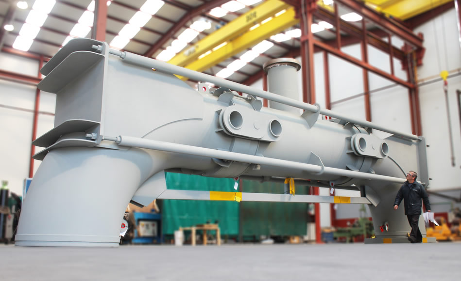
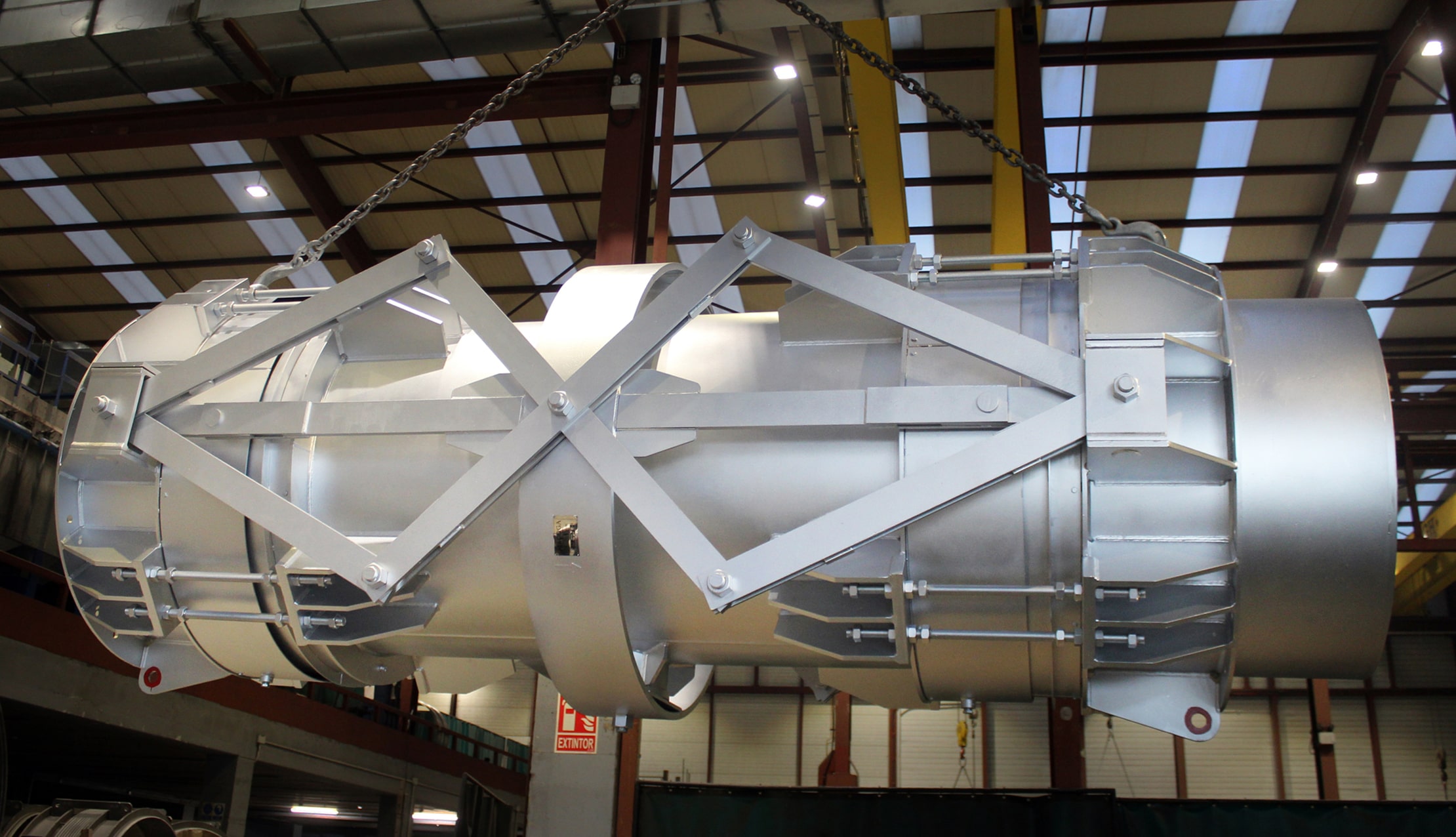
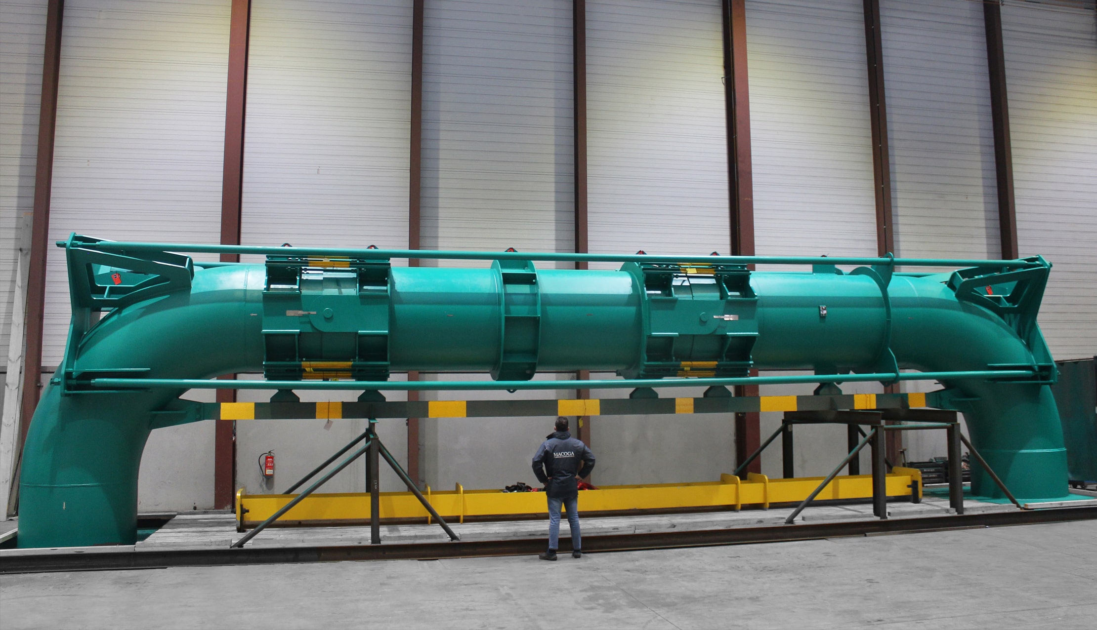
Expansion joints used in FCCU service are exposed to high temperatures, high pressures, large movement conditions and very aggressive media and therefore they are considered highly engineered units and one of the most critical and complex types of expansion joints manufactured.

The design of these expansion joints is complex because:

  • They must be suitable to operate at high process temperatures
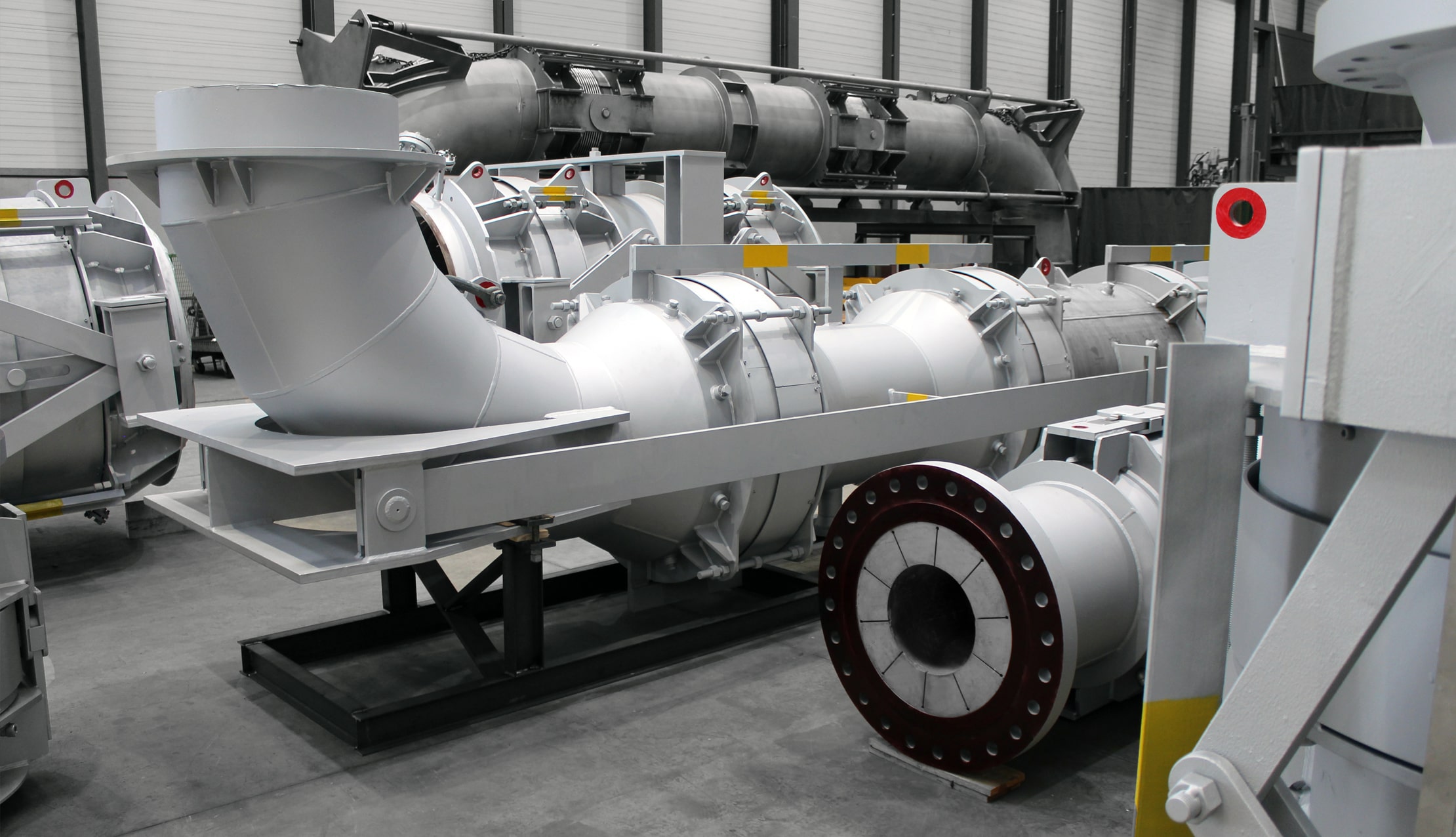
  • They must be resistant to erosion by catalyst
  • They must be resistant to corrosion and stress corrosion cracking during operation and shutdown conditions
  • They shall ensure an adequate fatigue life
  • They must absorb large movements
  • They shall ensure a good pressure resistance capacity while having a good flexibility

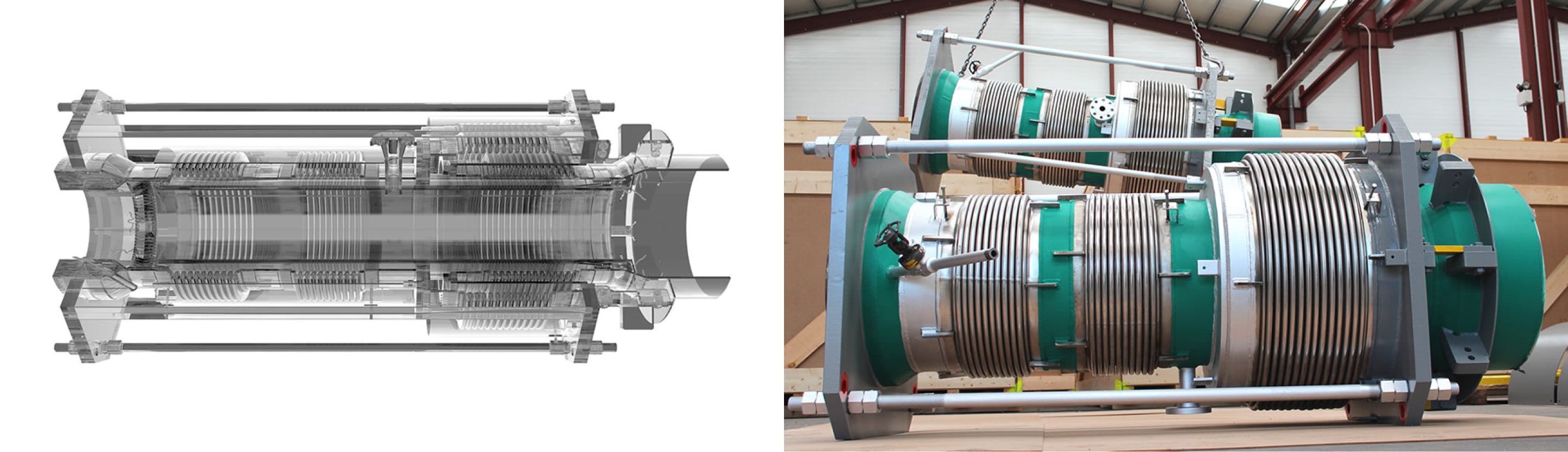
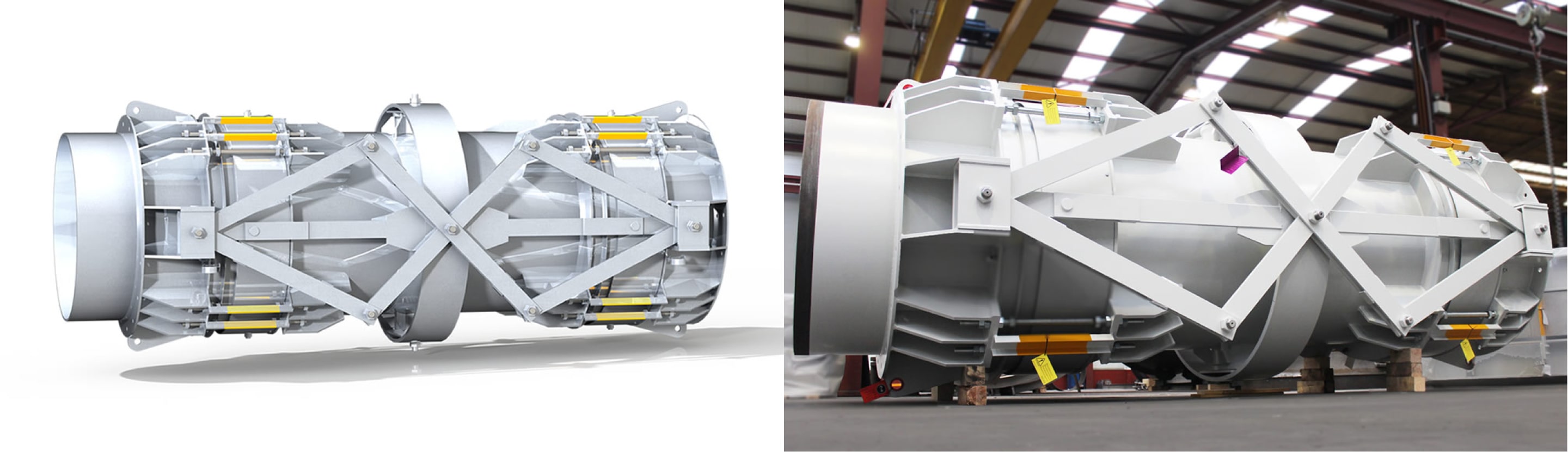
MACOGA has advanced capabilities to design and analyse FCCU Expansion Joints and all its components and accessories operating at high temperatures. Our analysis tools, e.g. non-linear finite element stress and heat transfer analysis (FEA) make possible to analyse complex components.

With our 3D mechanical CAD software our engineers design FCCU Expansion Joints to the same conditions that they’ll experience in the real world before they have been built. This is a design validation tool that helps our engineers to test the designs earlier in the design cycle and against real-world conditions. This lead us to improved design quality and manufacturing efficiency, while reducing time to market, costs and materials waste.

FEA/CFD
Our engineers are skilled in using Finite Element Analysis (FEA) and Computer Fluids Dynamics (CFD) to analyze the thermal-mechanical performance of different kind of systems.

Finite Element Analysis (FEA) based structural stress analysis is a valuable tool in the evaluation and optimization of product designs for systems including structural stress due to mechanical and thermal loading.

Using FEA/CFD as part of your product design process allows for the rapid and cost effective virtual testing and optimization of your designs. This will reduce overall product development costs, improving design performance and also give your team greater insights into how your design is likely to respond to a range of operating conditions.
Some samples of FEA/CFD studies:

  • Design/Analysis to ASME, API, PD and UNE standards
  • Stress analysis
  • Thermo-mechanical analysis
  • Heat transfer
  • Fatigue
  • Vibration Analysis
  • Dynamic analysis
  • Shock analysis
  • Resonance analysis
  • Coupled fluid structure interaction
  • HVAC analysis

The results obtained in this kind of analysis may be used to assess design safety as well as predict the expected fatigue life of the design.

Fluid Catalytic Cracking (FCC) technology involves high tech Expansion Joints and each technology provider has exclusive designs for these components. MACOGA has worked with all of the major FCC Technology Providers and is familiar with their designs.

FCCU Expansion joints are designed in accordance with:

  • ASME B 31.3 Appendix X
  • Expansion Joint Manufacturers
  • Association, Inc. (EJMA) Standards

and all applicable codes and specifications from licensors like UOP, KBR, ExxonMobil, Axens, etc.

Types

Typical types of expansion joints used in FCCU applications are: Restrained Universal, Gimbal, Hinged and Pressure Balanced (in-line and elbow type) and can be categorized in three major groups:

  • Hot Wall
  • Cold Wall
  • Unlined

The Cold Wall units are refractory lined to ensure the shell wall temperature does not exceed the allowed parameters. The lining consists of stainless steel anchors and a high-density vibrocast/self-levelled refractory material. They incorporate internal insulation/packing made of bio-soluble ceramic fibre or silica blankets, a liner seal that keeps in place
the internal insulation blankets while keeping fluid particles out of the bellows/liner cavity.

An important advantage of cold wall design Expansion Joints is that the pipe is insulated so

it operates below the media temperature reducing the pipe growth and consequently the expansion joint movement.

An insulation pillow is included to reduce the temperature. An external insulation is incorporated to prevent the bellows element from dropping below the acid dew point, the main reason of premature bellows failure.

The Hot Wall units incorporate an abrasion resistant lining, including hex-mesh and castable material or refractory (a multi-purpose abrasion resistant castable which can be hand-packed, vibration cast and gunned) such as RESCO AA-22. The lining is not intended to be used as a thermal fence and requires a specific and controlled drying.

The Unlined FCCU Expansion Joints can be exposed to very high temperatures but usually do not convey catalyst so they do not require abrasion resistant lining. This type is generally used for inlet and outlet air and transferring gases from the reactor.

The Bellows

The bellows, as the most critical part of the Expansion Joint, can be single ply, multiply, redundant ply or reinforced and generally incorporate an early warning system (active or passive monitoring).

FCCU expansion joints generally incorporate 2-ply testable bellows where each ply is designed for the full operating conditions. If a hole or stress crack develops in the inner ply during service, the outer ply takes over without exposing operators to increased risk or creating the need for an unscheduled shutdown.

2 ply testable bellows system improves reliability and makes the expansion joint more maintenance friendly.

Monitored Bellows

The annular space between plies can be monitored for leakage to detect a ply failure. This will serve as a warning of an imminent problem. A pressure device in the outer ply alerts about the inner ply failure. The 2-ply testable bellows also allows inspectors to pressure test the inner and outer ply during shutdowns. There are several types of devices used for monitoring the 2 ply testable bellows from simple pressure gauges to electronic devices and can be categorized as Active and Passive Monitors.

Passive monitor: when the inner ply fails the monitor is activated by the pressure between the plies.

Active monitor: the active monitor can detect inner and outer ply failures. A vacuum is created between the inner and outer ply before installing the monitoring device. If the inner ply fails, the pressure between the plies will activate the monitoring device and if the outer ply fails the vacuum will be lost and the monitoring device will be activated.

Packed Bellows

FCCU bellows are generally internally and externally packed with ceramic blankets and the gap between the sleeve and body is filled with a metal braided hose connected to the sleeve by pins. The thickness of the blankets is determined following heat transfer calculations to assure bellows temperature 200 < T < 500°C. The reason to specify the temperature of the bellows at a temperature higher than 200 °C, is to prevent dew point corrosion. The upper limit of 500 °C was to prevent high temperature embrittlement of lnconel 625.

To avoid the dust entering into the bellows cavity as the catalyst can solidify and damage the bellows or restrain the movement capability packed or purged bellows are used. The most frequent is the packed bellows. Purged bellows are not as commonly used today.

Self-equalizing rings

Are commonly used on FCCU Expansion Joints to prevent the convolutions from contacting each other ensuring a uniform compression distribution over the convolutions.

Equalizing rings prevent bellows from an excessive deflection or stress concentration in one or a few convolutions by spreading the movements over all the corrugations.

They also provide a pressure reinforcement capacity when necessary.


Materials selection

Bellows

The material for bellows for most FCCU applications is Inconel 625LCF. INCONEL® alloy 625LCF (UNS N06626 / W. Nr. 2.4856) developed as a fatigue- resistant, bellows-quality version of INCONEL alloy 625.

The fatigue life of alloy 625LCF can be up to 100 times that of conventional alloy 625. This can result in greatly improved service life over that possible with conventional alloy 625 products.

Inconel 625LCF is the best commercially available material for FCCU bellows in an external expansion joint. This material provides excellent stress corrosion cracking resistance, very good general high and low temperature corrosion resistance and very good mechanical properties including fatigue properties.

Some specifications require for the bellows to be annealed, or solution annealed, after forming.

Pipe body

The pipe body for the bellows in hot wall piping systems where operating temperatures are higher than 600 °C, is manufactured from stainless steel Type 304 or 321 H SS. For both materials the carbon content is often restricted to 0.4 < C < 0.6%.

In hot wall piping systems where the maximum operating temperatures are 500 < 600°C, the low Alloy steels like 1.25 Cr - 0.5 Mo are used.

In cold wall piping systems where the maximum operating temperature is 343 °C, fine grain carbon steel like ASTM A 516 Gr. 70 is used. No special requirements apply.


Refractory materials & installation

Refractory is a major element of all FCC components. Without proper refractory installation the process unit is risking a costly unscheduled unit shutdown. FCC Expansion Joints are designed with a hot wall (external insulation) or cold wall (internal insulating refractory). The internals that are exposed to catalyst erosion are protected with abrasion resistant refractory even in hot wall designs.

Generally, all these critical linings are designed and installed according to the most up-to-date and demanding refractory licensors specifications as UOP 3-series, ExxonMobil Research and Engineering EMRE Gp, KBR and API 936 or proprietary own specifications.

The insulating or abrasion resistant refractory linings can be installed by casting, gunning (pneumatic application), hand-placing or pneumatic ramming. The abrasion resistant refractory installation involves several critical activities like anchor system (hexmesh or equivalent), QC of materials, prequalification, application and heat dry outs. It is very important that all refractory installation activities are, during all the process, carefully controlled to ensure a good quality control through a good method of statement with drawings, materials selection, testing frequency, installation systems and dry out curve.

External hardware

FCCU joints usually fit in different types of external hardware. The most widely used are:

  • Control Rods
  • Pantographic linkages
  • Slotted Hinges and pantograph central bar
  • Central Gimbal

Control rods

Used to control and limit the movement of the bellows. Devices, usually in the form of rods ( 30 mm diameter minimum ), attached to the expansion joints assembly whose primary function is to restrain the bellows movements (axial, lateral and angular) during normal operation. Four control rods are normally provided at each bellows element. The rods are equally spaced circumferentially. Control rods are not designed to restrain pressure thrust.

Pantographic linkages

In universal expansion joints the pantographic linkages ensure that each bellows absorbs exactly half of the total bellows movements.
In case of vertical or inclined installation, the function of the pantograph linkage is also to supporting the weight of the connecting pipe of the two bellows, including refractory and medium weight. Pantograph linkage is not designed to restrain pressure thrust.

Slotted hinges and pantograph central bar

Slotted hinges installed in a universal expansion joint ensure that each bellows absorbs the same axial movement only. In case of horizontal installation slotted hinges also support the weight of the connecting pipe of the two bellows, including refractory and medium weight.

A pantograph central bar other than the same function of the slotted hinge, in case of vertical or inclined installation, can support one component of the weight of the connecting pipe of the two bellows, including refractory and medium weight. A pantograph central bar is always assembled with the pantograph linkage.

Central gimbal

A central gimbal system must be installed in universal untied expansion joints, where a pantograph linkage is mounted and if the required out of plane lateral movement is more than 10 mm.

The primary function of the central gimbal is, in presence of the pantograph linkage, to permit large lateral movements out of plane. The central gimbal is also designed to take the weight of the connecting pipe of the two bellows, including refractory and medium weight.


Expansion Joints for Fluid Catalytic Cracking Units (FCCU)

Premium Emergency Service

Learn more