Products

Metal Expansion Joints

Movements

There are three basic movements that can be absorbed by an Expansion Joint:

Axial movement

It is the change in dimensional length of the bellows from its free length in a direction parallel to its longitudinal axis. Can be either extension or compression.

Angular movement

It is the rotational displacement of the longitudinal axis of the bellows toward a point of rotation or bending of the expansion joint along its centerline.

Lateral movement

It is the relative displacement of one end of the bellows to the other end in a direction perpendicular to its longitudinal axis.

Metal Expansion Joints main parts and accessories

The basic unit of every expansion joint is the bellows. By adding additional components and accessories, the complexity and capability of the expansion joints is increased making them suitable for a wide range of applications and services.

These are some of the main and basic Expansion Joints accessories and components.
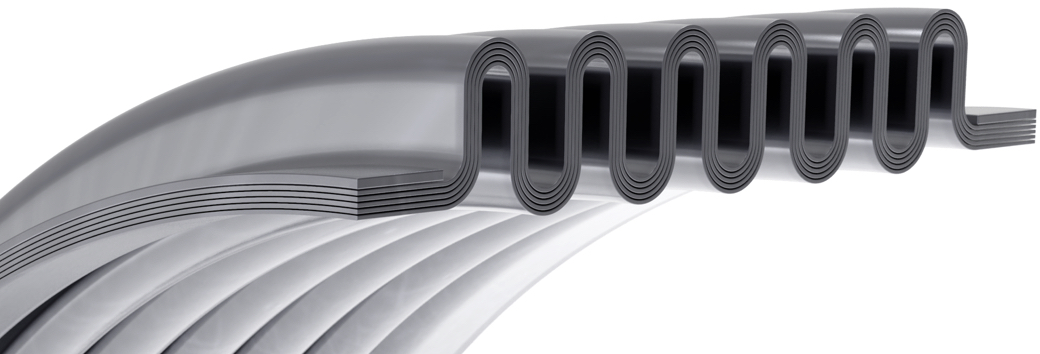
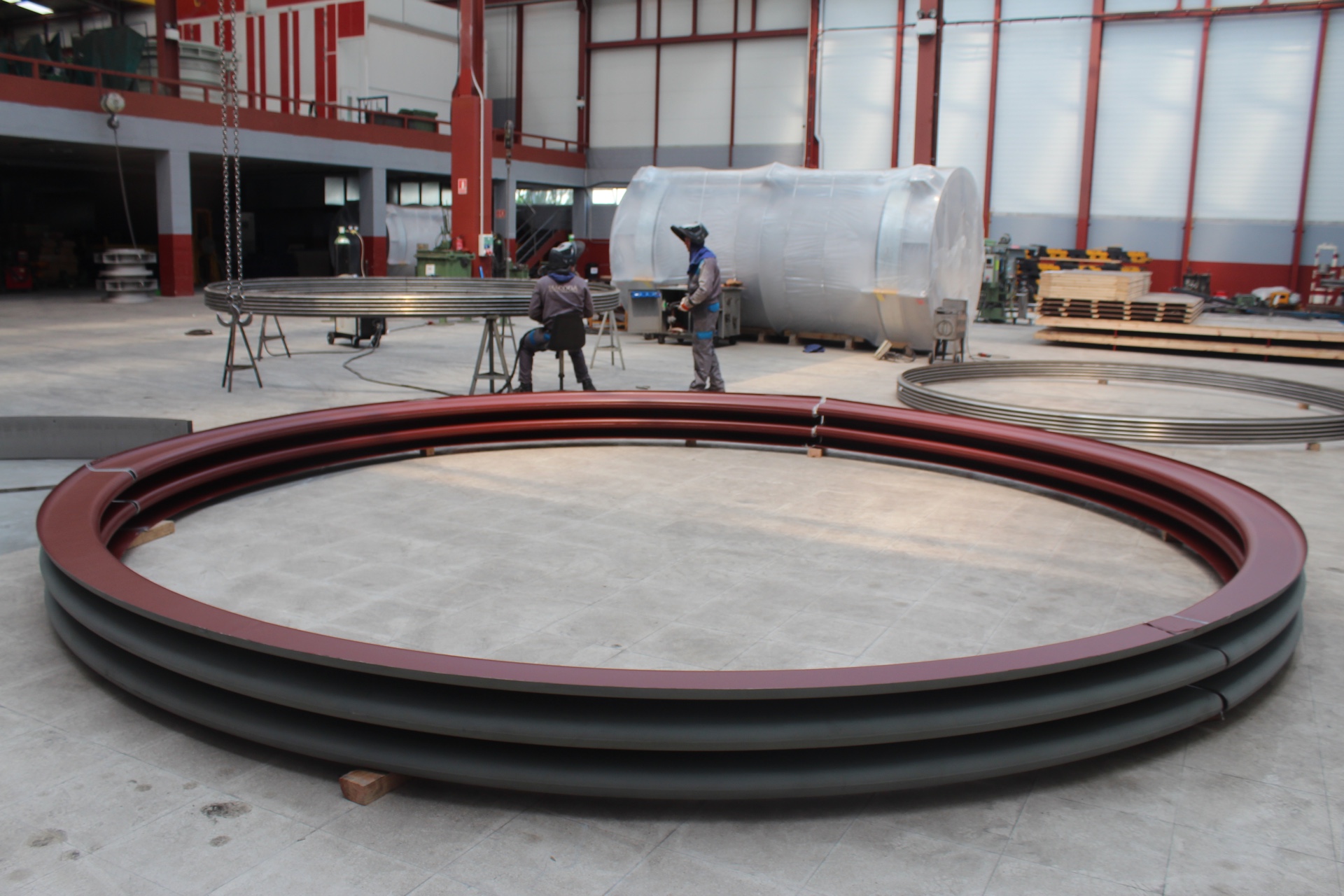
Bellows

A flexible element consisting of one or more corrugations and the end tangents.
The bellows can be singleply or multiply.

End tangents

The straight un-convoluted portions at the end of the bellows.

Connections

The most common types of connection parts are weld ends or flanges. In some cases male or female threaded ends are used.

Weld ends

The ends of an expansion joint equipped with pipe for weld attachment to adjacent equipment or piping. Weld ends are commonly supplied beveled for butt welding.
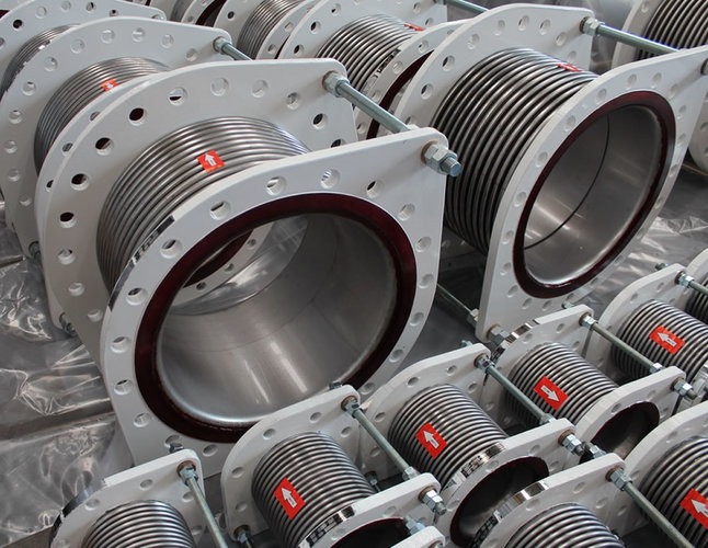
Flanged ends

The ends of an expansion joint equipped with flanges for the purpose of bolting the expansion joint to the matting flange of adjacent equipment or piping.
Flanged ends can be supplied fixed or swivel.

Metal expansion joint - Weld Ends Example Metal expansion joint - Weld Ends Example
Metal expansion joint - Flanged Ends Example Metal expansion joint - Flanged Ends Example

Reinforcing collars

Reinforcing sleeve or ring attached to the end tangent for reinforcement.

Assisting collar

Ring placed around the end tangents to facilitate welding.

Reinforcing and equalizing rings

Devices fitting snugly in the roots of the corrugations in order to reinforce the bellows against internal pressure, and/or to distribute axial movement equally to all convolutions while limiting amount of compression movement per convolution.
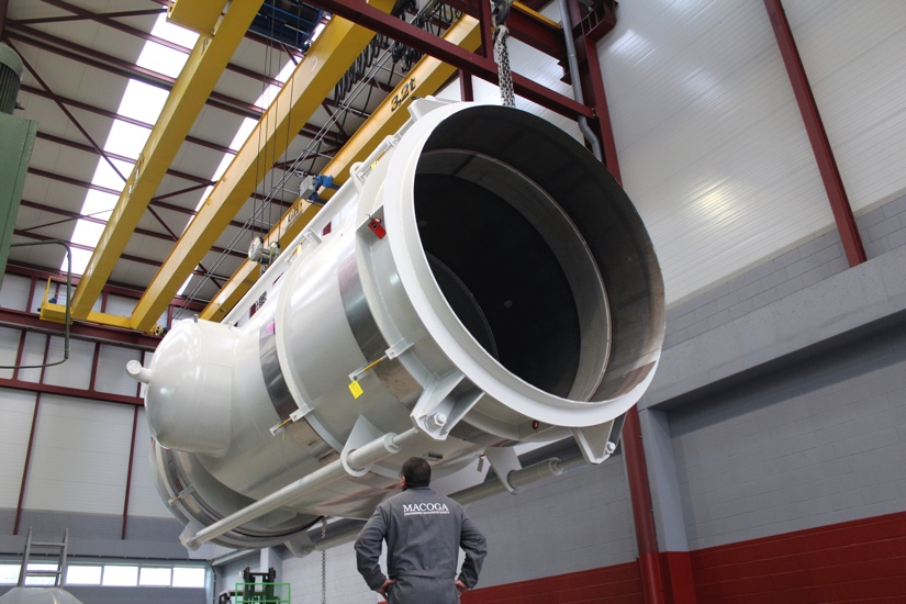
Metal expansion joint - Collars Rings Example Metal expansion joint - Collars Rings Example

Internal sleeve

A device which minimizes contact between the inner surface of the bellows of an expansion joint and the fluid flowing through it. These devices have also been referred to as liners or baffles.

Internal sleeves shall be specified for all Expansion Joints in the following cases:

  • When flow velocities are high and could induce resonant vibration of the bellows.
  • When it is necessary to hold friction losses to a minimum and smooth flow is desired.
  • When there is a possibility of erosion, as in lines carrying catalyst or other abrasive media, heavy gauge sleeves must be used. At no time should the relatively thin bellows be directly exposed to erosion.
  • When there is reverse flow, heavy gauge sleeves may be required, or the use of telescopic sleeves may be appropriate.
  • For high temperature applications to decrease the temperature of the bellows and enable the bellows metal to retain its higher physical properties. The annular area between the bellows and liner may be packed with ceramic fiber insulation, or a gas purge may be installed to further reduce the bellows effective temperature.

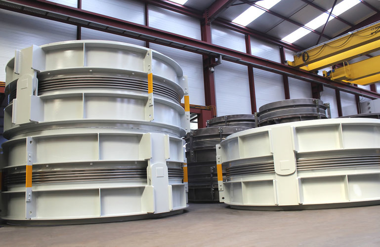
External cover or external sleeve

A device used to provide external protection to the bellows form foreign objects, mechanical damage and/or external flow and may act as a support for external thermal insulation.
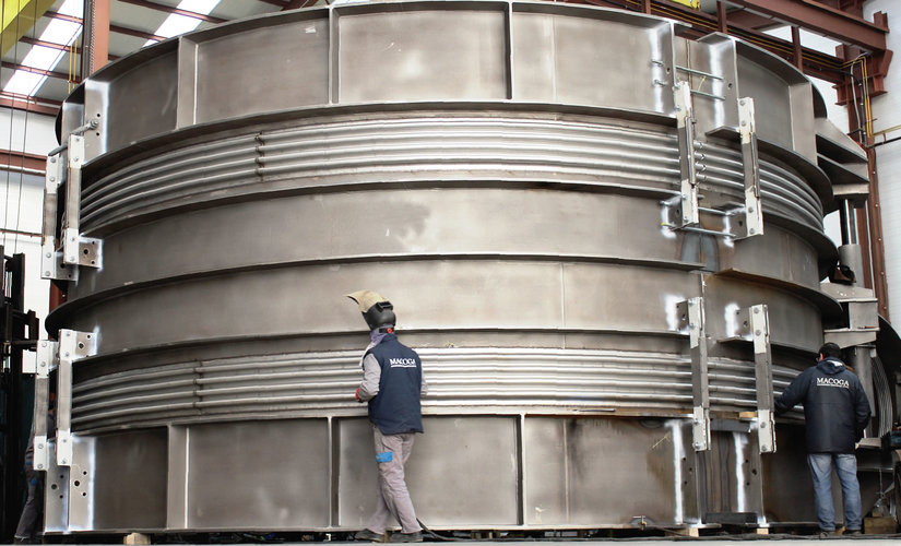
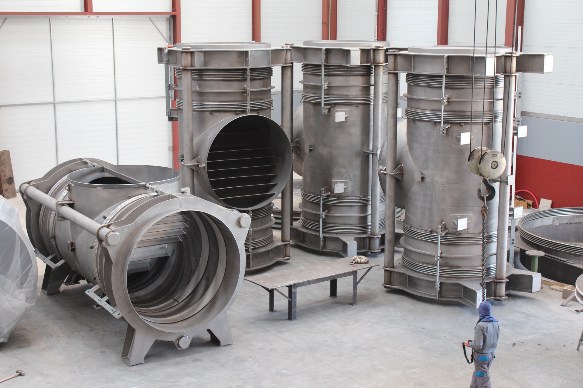
Metal expansion joint - Internal External Sleeve Example Metal expansion joint - Internal External Sleeve Example

Tie rods

Devices, usually in the form of rods or bars, attached to the expansion joint assembly whose primary function is to continuously restrain the full bellows pressure thrust during normal operation while permitting only lateral deflection. Angular rotation can be accommodated only if two tie rods are used and located 90° opposed to the direction of rotation.

Control rods

Devices, usually in the form of rods or bars, attached to the Expansion Joint assembly whose primary function is to distribute the movement between the two bellows of a universal Expansion Joint. Control rods are not designed to restrain bellows pressure thrust.

Limit rods

Devices, usually in the form of rods or bars, attached to the expansion joint assembly whose primary function is to restrict the bellows movement range (axial, lateral and angular) during normal operation. In the event of a main anchor failure, they are designed to prevent bellows over-extension or over-compression while restraining the full pressure loading and dynamic forces generated by the anchor failure.

Metal expansion joint - Rods Example Metal expansion joint - Rods Example

Hinged System

Hinged Expansion Joints incorporate a system of articulated supports (a pair of pins through hinge plates attached to the pipe expansion joint ends) which allow for angular movement in one plane only. The hinges and hinge pins must be designed to restrain the thrust of the Expansion Joint due to pressure and extraneous forces, where applicable.
These units do not allow axial movement however, some types of hinge systems can be provided with holes for the hinge pin that are slotted to allow limited axial displacement. These “slotted hinge” types cannot resist the pressure thrust forces and therefore proper anchorage must be provided.

Metal expansion joint - Hinged Example Metal expansion joint - Hinged Example

Gimbal or Cardam System

The gimbal system consists in two pairs of hinges affixed to a common floating gimbal ring.
A gimbal ring is either round or square. For round gimbals the torsional moment shall be considered and for square gimbals the instability due to the bending shall be considered.
Gimbal Expansion Joints are designed to allow angular movement in any plane and the gimbal ring, hinged and pins are designed to restrain the pressure thrust due to internal pressure and shear forces.

Metal expansion joint - Gimbal Example Metal expansion joint - Gimbal Example

Pantographic linkages

A scissors-like device. A special form of control rod attached to the expansion joint
assembly whose primary function is to positively distribute the movement equally
between the two bellows of the universal joint throughout its full range of movement.
Pantograph linkages, like control rods, are not designed to restrain pressure thrust.

Metal expansion joint - Pantographic Linkages Example Metal expansion joint - Pantographic Linkages Example

How metal bellows are formed?

Each manufacturer uses their own methods to manufacture metal bellows although in all cases the bellows are manufactured using seamless tubes or metal cylinders welded along their length.

Depending upon a range of different contributing factors (e.g. diameters, the number of sheets used, the materials used, etc.), the following are the most commonly used bellows forming methods:

Expansion (Expanding Mandrel) Forming

Individual convolutions are formed in a tube by an expanding internal mandrel. Flat spots are minimized by expanding the mandrel partially, and rotating the tube slightly. This process is repeated until an intermediate convolution height is achieved. Each convolution is subsequently sized by means of specially contoured inner and outer rollers.

Hydraulic Forming

A tube is placed in a hydraulic press or bellows forming machine. Circular external die rings of suitable contour are placed outside the tube at longitudinal intervals approximately equal to the developed length of the completed convolutions. The tube is filled with a medium such as water and pressurized until circumferential yielding occurs. This forming operation continues with a simultaneous circumferential yielding and controlled longitudinal shortening of the tube until the proper configuration is obtained. Individual or multiple convolutions may be formed by this method. Depending on the bellows configuration, several partial-forming steps with intermediate heat treatment may be required. Reinforced bellows may be formed by utilizing external reinforcing rings that act as part of the forming dies. After completion, when the dies are removed, the rings remain as an integral part of the bellows.

Elastomeric Forming

A longitudinal welded tube is inserted over a mandrel containing a rubber torus. Axial force on the mandrel expands the torus, forming a bulge in the tube. The torus is then relaxed and the bulge is axially compressed into a convolution by external dies. Convolutions are formed one at a time. The tube is free to shorten as the convolution is formed.

Roll Forming

A tube is placed in a forming machine and individual or multiple convolutions are formed by means of pressure exerted by forming wheels. Generally, the wheels are on both the inside and outside of the tube. Controlled longitudinal shortening of the bellows tube occurs during the forming operation. The tube may rotate about fixed-shaft forming wheels, or the tube may be fixed and the wheels rotated about the tube's circumference.

Press-Brake Forming

A flat sheet is convoluted using a press-brake die to form the individual convolutions. This method is used primarily in the manufacture of bellows for rectangular Expansion Joints. The most common styles are the "U" profile and "V" profiles.

Multiply Bellows

The use of circular multiply bellows are the ideal solution for Expansion Joints which are exposed to high pressures. This system involves constructing a bellows using several thin sheets instead of one single thick ply. This technique considerably improves the flexibility of the bellows, its most important characteristic.

Metal expansion joint - Pantographic Linkages Example

Main advantages to be gained from using multiply metal bellows:

  • They are highly resistant to high pressures.
  • They maintain a high degree of flexibility even when working under high pressures.
  • They have lower spring rates than the single thick sheet bellows.
  • They have a high absorption rate for movements across short lengths thus ensuring a longer working life.
  • Possibility of leak detection holes for early indication of leakage.
  • Possibility of installing leak detectors for critical media.

They guarantee important savings:

  • Few units are required within any given system owing to their greater capacity to absorb movements.
  • The low spring rates reduce the costs incurred by anchorage and supporting structures.
  • To avoid corrosion, special materials (eg. Inconel, Incoloy, etc.) can be applied to the inner layer in order to protect against temperature and corrosion and austenitic steel can be used to cover the remaining layers in order to withstand high pressures.
Metal expansion joint example 1 Metal expansion joint example 2

Design & manufacturing

Standards

MACOGA Expansion Joints are designed, manufactured and tested in accordance with:

  • E.J.M.A. (Expansion Joint Manufacturers Association, Inc.)
  • ASME VIII, Div. I, App. 26
  • EN 14917, European Standard for Metal Expansion Joints.

If specially requested or included in the terms of the contract, the Expansion Joints can also be designed according to other international standards and codes (AD-Merkblatter B13, CODAP, etc.).

Design control and modifications are set out in the latest version of our Quality Control Manual and the Quality Procedure "Design and Calculation".

Metal Expansion Joints and Metal Bellows

Manufacturing Range

Circular Expansion Joints are manufactured with single or multiple ply with a diameter ranging from 15 to 10000 mm.

Our manufacturing range includes Circular Expansion Joints of the following types:

  • Single Unrestrained
  • Single Tied
  • Universal Unrestrained
  • Universal Tied
  • Hinged
  • Double Hinged
  • Gimbal
  • Double Articulated
  • Double Gimbal
  • Pressure Balanced
  • Flanged & FluedExternally Pressurized
  • Jacketed
  • Reinforced High Pressure
  • Thick Wall Lens and MUX Series
  • Rectangular
  • PTFE Lined
  • Two Ply Testable
  • Special Shapes

As well as Rectangular Expansion Joints which, with limitless dimensions, can be supplied with different convolution and corner types:

  • W-shaped, Camera Corner
  • V-shaped, Miter Corner (single or double)
  • U-shaped, Rounded Corner

Materials Used

The essential component of an Expansion Joint resides in the degree flexibility of its bellows and this depends upon the design of its convolution and the materials used during the production process.

The choice of metals to be used in manufacturing the bellows, being the basic component of the Expansion Joint, is made taking the following criteria into account:

  • Temperature resistance.
  • Resistance to corrosion.
  • Forming capacity.
  • Mechanical characteristics.
  • Resistance to fatigue.
  • Flexibility when in use.

The tables shows the materials mostly used to produce our bellows:

Name ASTM UNS EN
304 304 S30400 1.4301 Austenitic
General Service
304L 304L S30403 1.4306
316 316 S31600 1.4401
316L 316L S31603 1.4404
316H S31609 1.4401/1.4919 -
316Ti 316Ti 1.4571 1.4571
321 321 S32100 1.4541
904L 904L N08904 1.4539
254 SMO S31254 S31254 1.4547
304H 304H S30409 1.4948 Austenitic
Heat Resisting
321H 321H S32109 1.4878
309S 309S S30908 1.4833
310S 310S S31008 1.4845
253 MA S30815 S30815 1.4835
Stainless steel grades

254 SMO and 253 MA are trademarks of Outokumpu Stainless

Name UNS EN
Inconel 600 N06600 2.4816
Monel 400 N04400 2.4360, 2.4361
Inconel 625 N06625 2.4856
Inconel 625LCF N06625 2.4856
Incoloy 800 N08800 1.4876
Incoloy 800H N08810 1.4958
Incoloy 825 N08825 2.4858
Hastelloy C4 N06455 2.4610
Hastelloy C-22 N06022 2.4602
Hastelloy C-276 N10276 2.4819
Nickel Alloys

Inconel, Monel & Incoloy are trademarks of Special Metals Corporation. Hastelloy is a trademark of Haynes International, Inc.